
Diffraction Gratings
The diffraction grating is the main element in the optical system of a spectrometer that separates incident polychromatic radiation (white light) into monochromatic radiation (light of one color). It consists of a series of parallel grooves, equally spaced and formed in a reflective coating deposited onto a glass substrate. The distance between each groove and the angles the grooves form with the substrate influence both the dispersion and efficiency of a grating.
What are the key parameters when choosing the right grating for your spectrometer?
All spectrometers manufactured by Sarspec are equipped with fixed diffraction gratings that can be selected by the user according to the wavelength range of interest. The two key parameters when choosing the right grating for your spectrometer are the groove density which allows you to set the operational wavelength range and optical resolution and the grating groove efficiency for the selection of the wavelength range where your system sensitivity is at its maximum. Detailed information about these two parameters can be found in the following sections.
Grating Groove Density
The groove density or groove frequency is usually expressed in nm/mm and determines the range of wavelengths that are dispersed by the grating into the detector. The increase of the groove density (grooves (or lines)/mm) results in an improvement of the optical resolution for a certain slit width. On the other hand, groove density also defines the operational range of wavelengths of the grating, being that a higher groove density will generate shorter operational ranges for your spectrometer. Increasing the groove density leads to a higher optical resolution but also to a shorter wavelength operational range (see Figure 1).

Figure 1 – Absolute efficiency curve of 3 gratings with 1800 (orange) , 2400 (blue) and 3600 (black) grooves/mm.
Grating Efficiency
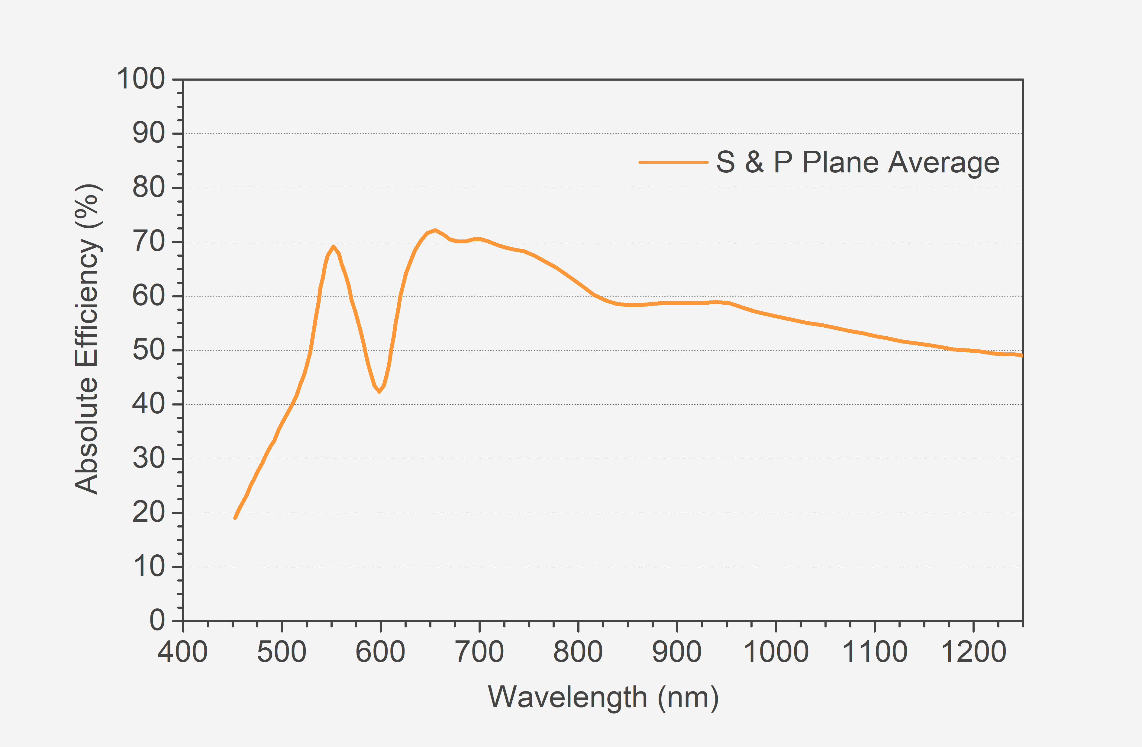
As grating diffracts the incident radiation, it does not do so with uniform efficiency. The overall shape of the grating efficiency curve (a plot of absolute or relative diffracted efficiency as a function of the diffracted wavelength) shows normally a single maximum, at the peak of maximum brightness (or blaze wavelength) and is generally a rather complex function of wavelength and polarization of the incident radiation and depends on the groove density, plane of polarization, shape, and angle of the grooves and the reflectance of the coating material.
In ruled and ruled holographic gratings, changing the groove angle (the angle created by the longer side of the groove and the plane of the grating) moves the diffracted radiation along the spectral region and changes the blaze wavelength. When selecting the best grating for your spectrometer, take into consideration the grating efficiency – its maximum will, normally (also depending on the efficiency curve of the detector), correspond to the maximum sensitivity of the operational wavelength range (see Figure 2).
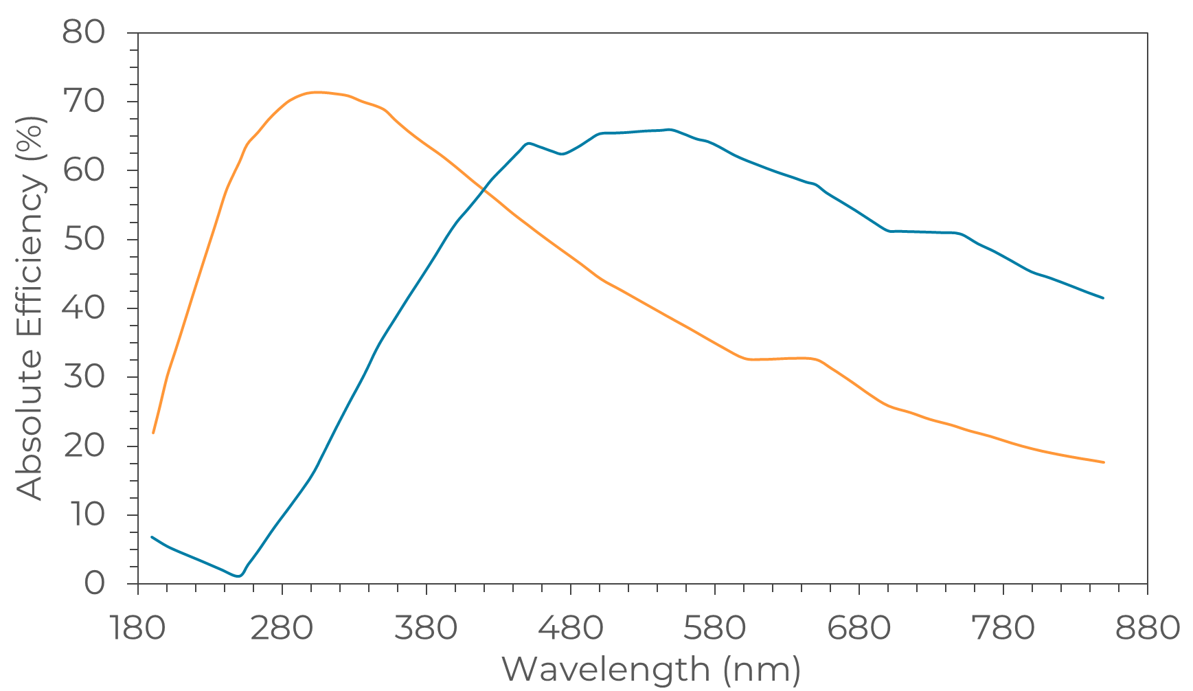
Figure 2 – Absolute efficiency curve of two 600 grooves/mm gratings, maximum efficiency peaks at 300 nm (orange) and 500 nm (blue).
Which types of gratings are used in our spectrometers?
Sarspec uses regularly three types of gratings in its spectrometers depending on the purpose of the application and required specifications. A brief description of Ruled, Holographic, and Blazed Holographic grating can be found within the following sections.
Ruled Gratings
Ruled gratings are produced by physically forming a series of triangular grooves onto the surface of a substrate, using a diamond tool mounted on a ruling engine. The slope of the triangular groove is usually adjusted to improve the brightness of the grating at a specific wavelength. Once the triangular grooves have been formed, the substrate is coated with a highly reflective material, see Figure 3.
The drawback of ruled diffraction gratings is that due to the nature of the production process, they have defects that can occur in the form of periodic errors, surface irregularities, or spacing errors. As a consequence of these defects, ruled gratings have increased stray light and ghosting effects.

Figure 3 – Design of a Rulled Grating
Holographic Gratings
Holographic gratings are produced by interfering with two laser beams to create a sinusoidal pattern on the surface of the substrate, then coating it with a highly reflective material, see Figure 4.
While ruled gratings offer higher efficiencies at a particular wavelength (blazed wavelength), they suffer from periodic errors in groove production, therefore generating high amounts of stray light. With holographic gratings, these errors are strongly reduced. The drawback of holographic gratings when compared to blazed gratings is reduced efficiency.

Figure 4 – Design of a Holographic Grating
Blazed Holographic Gratings
The advantages of both ruled and holographic gratings can be combined into the so-called blazed holographic gratings. The grooves on a blazed holographic grating are produced by applying a two-laser-beam-interference method, which is the same method used to produce conventional holographic gratings. Then, the ion-beam etching technique creates the standard “sawtooth” design that is used in conventional ruled gratings.
Because there is no need for mechanical ruling, the periodic structure errors found in conventional ruled grating are no longer present, and that ensures less amount of stray light and ghosting. Owing to their high efficiency and minimal stray light and ghosting, blazed holographic gratings are the ideal optical components to be used in instrumentation that require extreme efficiency and resolution and are included as standard in our UV/Vis, UV/Vis/NIR and Vis/NIR configurations.
Available gratings to configure your spectrometer
| Spectral Region | Spectral Range (nm) |
Groove Density (grooves/mm) |
Peak Wavelength (nm) |
Grating Efficiency Curve | Order Information |
|---|---|---|---|---|---|
| UV | 190 - 390 | 1800 | 240 | See Figure | G-UV |
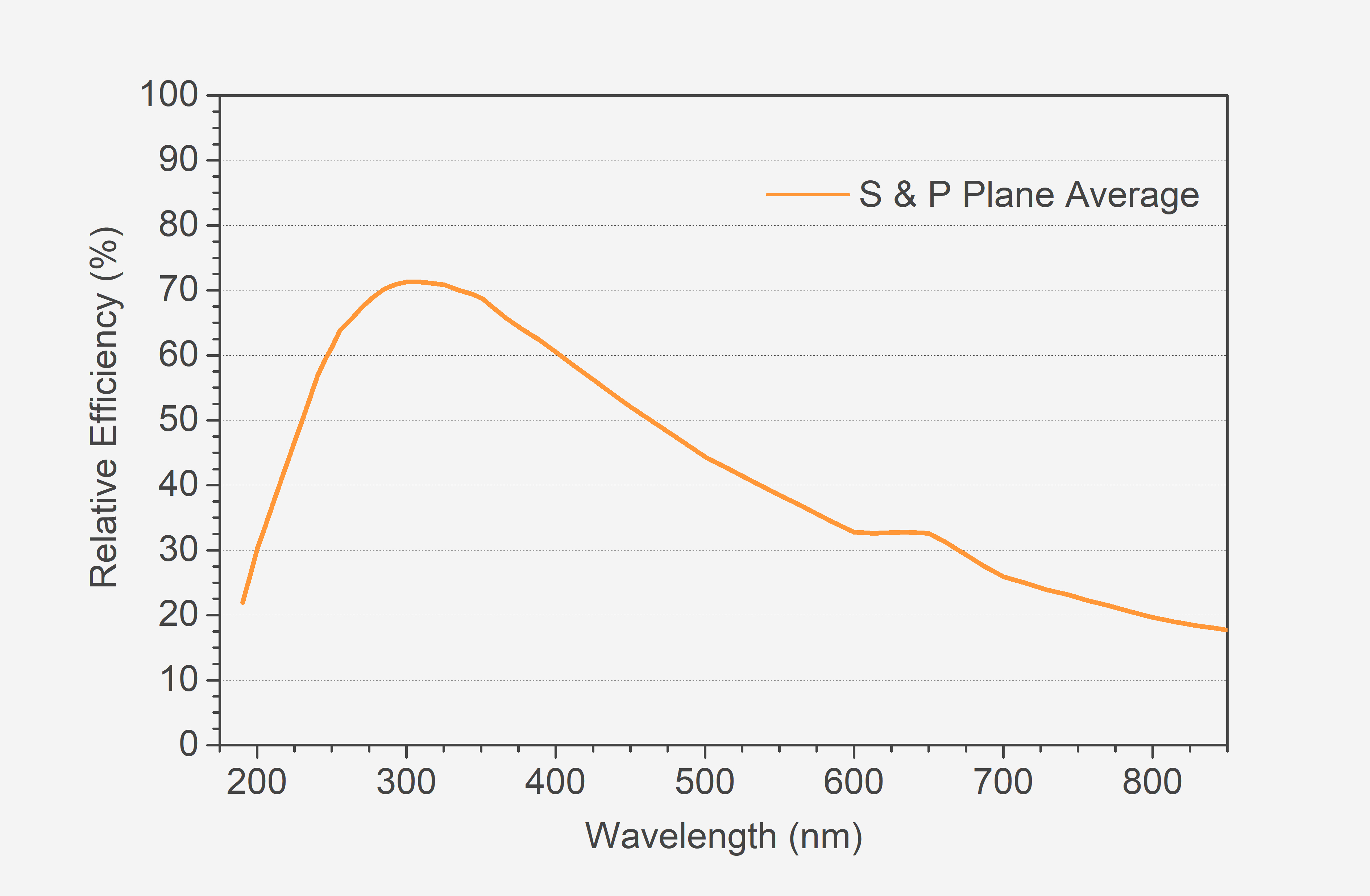
| UV / Vis* | 190 - 900 | 600 | 300 | See Figure | G-UV-Vis |
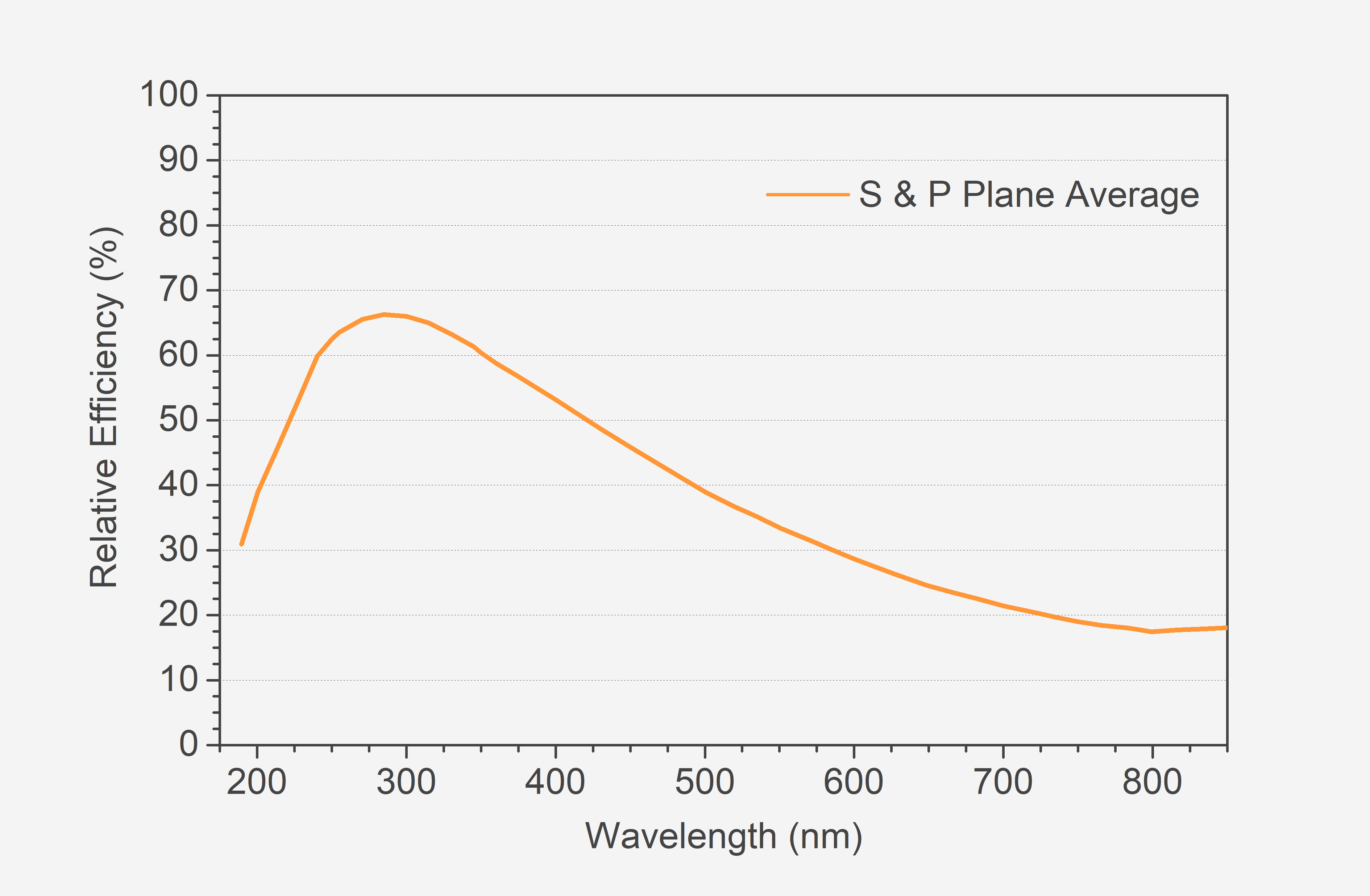
| UV / Vis / NIR* | 190 - 1100 | 500 | 300 | See Figure | G-UV-Vis-NIR |
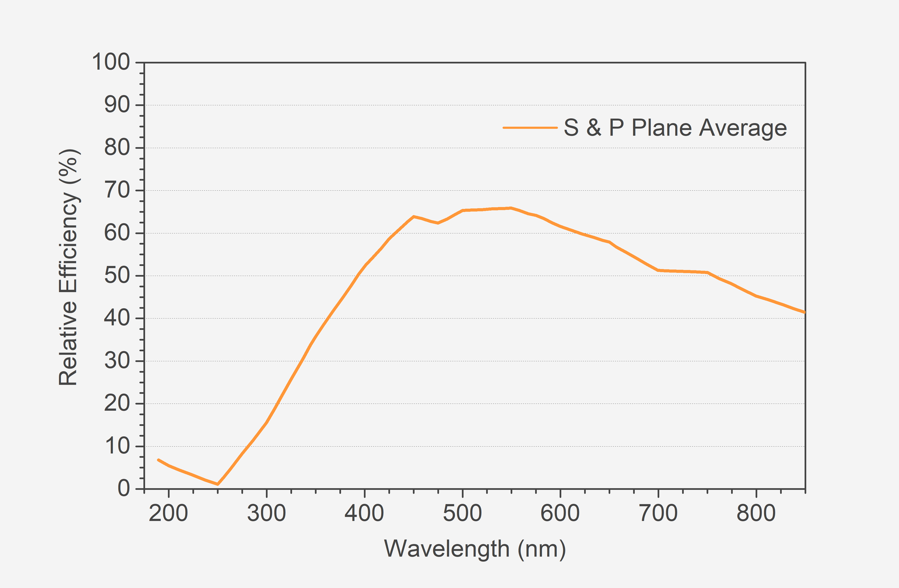
| Vis | 360 - 700 | 1200 | 500 | See Figure | G-Vis |
| Vis / NIR* | 360 - 1100 | 600 | 500 | See Figure | G-Vis-NIR |
| NIR | 680 - 1100 | 1200 | 750 | See Figure | G-NIR |
*Blazed Holographic Gratings